
Introduction to Electric Shock Protection Study
Electric shock protection study is a study carried out to calculate and evaluation of maximum voltage the personnel may be exposed to (touch voltage), proper earthing system, current carrying capacity and size protective earthing (PE) cable, loop impedance, loop current, rating and disconnecting time of shock protection devices such as Ground Fault Current Interrupter (GFCI) or Residual Current Circuit Breaker (RCCB) or Residual Current Detector (RCD). Sometimes, shock protection analysis is include in load flow, short circuit and protection coordination analysis studies, and closely related arc flash studies. This study is an engineering control measure of the hazard control hierarchy in occupational safety management — Omazaki Consulant is a consultant that provides electric shock protection analysis study consulting service. Contact us if you are looking for consultants who serve electric shock protection studies consultancy services for your electricity systems in Indonesia and South East Asia by sending an email to cs@omazaki.co.id or by filling in the form in contact. Our electric shock protection analysis study mostly using ETAP software.
This article presents an overview of basic knowledge of electric shocks, general shock protection systems, and studies of electric shock protection design. We will only focus on the engineering design aspects of the electrical system to prevent the impact of a severe electric shock .
———————————————
Basic Knowledge
What is Electric Shock?
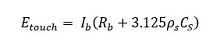
Electric shock is a physical stimulation that occurs when an electric current flows through the human body. The current that flows through the body carries energy in the form of heat. The amount of energy can be estimated by:

Electrical shock occurs when a person touches any electrically charged object while at the same time touching another surface that can conduct the electricity to the ground. Common sources of electrical shock are bare and damaged wires, machinery and tools, and extension cords. Proper grounding and electrical safety devices can help prevent electrical shock.
Electric Shock Effect to Human Body
Based on international studies 95% of adults are considered to have a body impedance in the range of 1000 to 2000 ohms. In the event of a 230 volt supply combined with 1000 ohms body resistance, a current of up to 230 milliamps may flow through the body. This presents a serious and potentially fatal shock risk.

Five factors are important in understanding the risk of electrical shock:
- The magnitude of the current.
- The duration of the current.
- The path it takes in the human body.
- The resistance of the body.
- The frequency of the electrical supply.
Direct and Indirect Contact
IEC 61140 standards distinguish two kinds of dangerous contact, Direct contact and Indirect contact.
- Direct contact refers to a person coming into contact with a conductor which is live in normal circumstances.
- Indirect contact refers to a person coming into contact with any part of a electric circuit which is not normally live, but has become live due to an accidental insulation failure or some other fault.
Touch Voltage
Touch voltage is potential difference between the ground potential rise (GPR) on the ground where the network or system is located and the potential of the surface on which a person is standing while touching a structure connected to the ground. .

The mathematical equation for touch voltage is given by:
The IEC standard specifies a safe touch voltage below 50V for alternating current (AC) systems and maksimum 120V for direct current (AC) systems.
———————————————
Fundamental of Electric Shock Protection
The basic rule of protection against electric shock is that live parts must be inaccessible and conductive parts that are accessible so that the voltage must not exceed the safe limit. This is true both under normal conditions and in conditions of single disturbance or fault.
Under Normal Condition (Basic Protection)
Protection under normal conditions is provided by basic protection. Basic protection prevent contact with live parts, such protection by the insulation of live parts and protection by means of barriers or enclosures.
Under Fault Condition
Protection under a single fault condition is provided by fault protection. Fault protection can be achieved by automatic disconnection of the supply where the conductive parts of the apparatus are properly grounded .
Enhanced Protective
Protection against electric shock is provided by an enhanced protective provision, which provides protection under normal conditions and under single fault.
Engineering Control Measure to Prevent Electric Shock
Based on IEC 60364-4-41, the following protective measures generally are permitted:
- Automatic disconnection of supply (Clause 411),
- Double or reinforced insulation (Clause 412),
- Electrical separation for the supply of one item of current-using equipment (Clause 413),
- Extra-low-voltage (SELV and PELV) (Clause 414).
Earthing System
The heart of any electric shock protection system is an earthing system. For a full understanding of electric shock protection it is necessary to consider the different types of earthing system in use. To provide earthing for an installation, an earthing terminal is needed. This is achieved using one of five different methods:
- TN-C System – the neutral and the earth terminals are combined.
- TN-S System – the neutral and earth terminals are completely separated.
- TN-C-S System – the neutral and earth terminals and combined, but the separated just outside the consumer’s installation.
- TT System – no earth terminal is provided, but the star point of the supply is connected to the mass of the earth, and the consumer’s installation is also connected to the mass of the earth. The earth at the consumer’s installation is usually provided by installing local earthing systems (e.g., rods or mats).
- IT System – this is similar to the TT system, with the difference that a resistor is inserted between the star point of the supply and the earth.
Electric shock protection study will focus on subject above.
———————————————
Why Need to Conduct Electric Shock Protection Analysis?
Electricity is a silent killer because it cannot be seen or heard. Statistically it has been shown that electric shock is one of the main causes of fatality in the workplace and homes. To ensure a negligibly small risk of electric shock in the built environment, designers and installers adopt good wiring practices and abide by the relevant national and international wiring rules, e.g. SNI PUIL and IEC 60364, to enable them to produce a safe electrical installation.
Electrical devices are frequently handled with currents and voltages which is inherently harmful to animals, humans and structures. Those dangers can be caused by physical interaction, overloading, short circuiting, and loss of component, or impact of heat or moisture.
———————————————
Electric Shock Protection Analysis Using ETAP
Methodology
Our methodology in proceed electric shock protection consulting service as engineering control measure in safety management is as follow:
- Data collection and verification
- Electric shock modelling
- Model verification and validation
- Simulation
- Under normal condition
- Under fault condition
- Analysis and recommendation
- Reporting
Deliverables
A detailed report is provided that includes:
- Description of the basis, purpose and scope of the study
- System and earthing description
- Tabulations of the data used to model system components and a corresponding one-line diagram
- Calculation and evaluation of:
- Touch voltage
- Current carrying capacity and size protective earthing (PE) cable
- Loop impedance
- Loop current calculation
- Rating and disconnecting time of shock protection devices
- Touch voltage
- Analysis and Recommendation
———————————————
 Contact Omazaki Engineering if you are looking for a electric shock protection analysis and study consultant who serves consulting service using ETAP software to help with your project or for other purposes related to your electrical system in Indonesia and South East Asia.
———————————————
Related Articles
- Power System Study & Analysis
- Short Circuit Study & Analysis
- Protection Coordination Study
- Arc Flash Study & Assessment
- Arc Flash: Definition, Hazards & Risks
- Arc Flash Causes Analysis
- Arc Flash Calculation Methods
- Arc Flash Boundary and Requirement of PPE
References
- IEC 60364-4-41 Low voltage electrical installations – Protection Against Electric Shock
- IEC 60479-1 Effects of current on human beings and livestock –Part 1: General aspects
- IEC61140 Protection against electric shock – Common aspects for installation and equipment
- NFPA 70EStandard for Electrical Safety in the Workplace
- The essentials of electric shock protection, earthing systems and RCDs, EEP.
- Electric Shock Protection – https://www.westernautomation.com/solution-centre/electrical-safety-applications/shock-protection/?doing_wp_cron=1618714149.9945919513702392578125
- Protection against electric shock, Electrical Installation Wiki
- Legrand – Power Guide 2009: Electrical Hazards and Protecting Persons
———————————————