
A passive harmonic filter is an electrical circuit consisting of a combination of capacitors (C) and inductors (L) arranged in such a way that they resonate at a specific frequency. In electrical power system, these passive filters function to suppress harmonic currents and reduce voltage distortion, especially in areas sensitive to power quality. —Omazaki Engineering is a consultant who provides passive harmonic filter design and calculation consulting services. Contact us if you need a passive harmonics filter designer service by emailing cs@omazaki.co.id or filling out the contact form.
———————————————
Introduction to Passive Harmonic Filter
The primary function of a passive harmonic filter is to utilize the impedance characteristics at the resonant frequency. A filter installed in series with the load will exhibit high impedance to certain harmonic frequencies, thereby inhibiting the flow of harmonics toward the load. However, in practice, a shunt (parallel) configuration is much more common.
In a shunt configuration, the filter is installed parallel to the load and provides a low-impedance path for harmonic currents, allowing them to flow to ground. Furthermore, this filter can provide capacitive reactive power at the fundamental frequency, which can also be used to improve the system’s power factor.
———————————————
Understanding Passive Harmonic Filter Design
Passive harmonic filter design refers to the technical planning process and calculation of the L and C components to be used, based on the characteristics of the harmonics occurring in the system. The main goal of this design is to create a filter that can effectively absorb dominant harmonics, without causing side effects such as parallel resonance or component overloading.
Some important things to consider when designing a passive filter include:
- Determine the filter tuning frequency based on the dominant harmonic (e.g., the 5th or 7th harmonic),
- Calculate the capacitance and inductance required to ensure the filter resonates at the target frequency,
- Ensure that the filter remains stable and safe under various operating conditions, both during normal system operation and during disturbances or load variations.
With proper design, passive harmonic filters can be an efficient and reliable solution for maintaining power quality, especially in industrial distribution systems that have significant nonlinear loads.
———————————————
Types of Passive Harmonic Filters
There are several types of passive harmonic filters commonly used in power systems, each with its own characteristics, advantages, and application areas. Selecting the appropriate filter type depends heavily on the harmonic spectrum to be controlled, as well as the efficiency and technical limitations of the system itself.
The following are the three types of passive harmonic filters most commonly used in industry:
Single-Tuned Filter
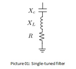
A single-tuned filter is the simplest and most widely used type of passive filter in the industrial world. This filter is designed to absorb one specific harmonic order, such as the 5th, 7th, or 11th harmonic. Its working principle is to create a very low impedance at the tuning frequency, so that the harmonic current at that frequency is directly “pulled” to ground through the filter.
Some of the key parameters in Single-Tuned Filter design are:
- Target harmonic order
- Rated reactive power (kVAR) to be supplied
- Quality factor (Q factor), which indicates the filtering bandwidth or selectivity. Q values are typically between 30–60.
Advantages of Single-Tuned Filters
- Provides near-perfect filtering at the target frequency.
- Simple and economical structure.
Disadvantages of Single-Tuned Filters
- Less effective for harmonics above the tuning frequency
- Resonance parallel to the system can occur at frequencies slightly below the tuning point, potentially amplifying other harmonics if not anticipated early.
High-Pass Filter
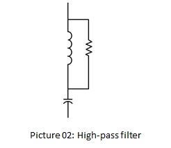
High-Pass Filters are designed to absorb high-frequency harmonics, typically from the 7th or 11th harmonic and above. These filters have a characteristic impedance that decreases with increasing frequency, making them suitable for use with a wide harmonic spectrum. Important characteristics of a high-pass filter include:
- The resistor serves to limit the maximum impedance at high frequencies (asymptotic limit)
- The bandwidth is determined by a low Q-factor (around 5–2.0)
- Suitable for damping high-frequency notch-type oscillations.
Important note:
Because the resistor in a high-pass filter absorbs power at the fundamental frequency, it is less suitable for filtering low-order harmonics (<5th), as it consumes large amounts of reactive power.
C-Type Filter
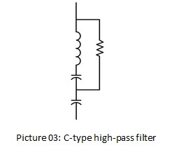
The C-Type has a similar structure to the HPF, but with additional L and C resistors that form a parallel resonance with the resistor at the fundamental frequency. This prevents current at 50/60 Hz from flowing through the resistor, resulting in no power losses at the fundamental frequency.
C-Type Advantages:
- High efficiency for low-order harmonics
- Resistor power consumption is almost zero under normal conditions
- Suitable for applications with heavy harmonic loads such as electric arc furnaces or cycloconverters.
The C-Type is generally used when extra damping is required while maintaining system efficiency, especially in heavy industrial systems.
———————————————
Passive Harmonic Filter Calculation Example
To further understand the passive harmonic filter design process, we present a numerical case study based on the guidelines in IEEE Std 1531-2020.
A 30 MVA industrial load is supplied from a 34.5 kV bus. The symmetrical three-phase fault level on the bus is 10,000 A (10 kA). The load has an initial power factor of 0.85 lagging, and it is expected to be improved to 0.95. Furthermore, this load is a source of harmonic currents, so the installed capacitor must not only function for power factor correction but also be designed as a harmonic filter.
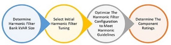
Step 1: Determining the kVAR Size of the Harmonic Filter Bank
The first step in designing a passive harmonic filter is to calculate the reactive power (kVAR) required to improve the system’s power factor. In this case study, a 30 MVA industrial load is supplied from a 34.5 kV bus, with an initial power factor of 0.85 lagging, and a target improvement to 0.95.
According to IEEE Std 1036 guidelines, the compensated reactive power value can be calculated based on the apparent power (kW) and a correction factor that depends on the initial and final power factor values. Because the actual power (kW) information is not directly provided, an approach based on the apparent power (kVA) and initial power factor is used.
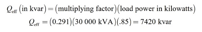
- The value of 0.291 is the multiplier from IEEE Standard 1036, which is appropriate for converting from a PF of 0.85 to 0.95.
- The calculation shows that 7420 kVAR (or 7.4 MVAR) of capacitors are required to compensate for the reactive power and achieve the target power factor.
Step 2: Determine the Initial Harmonic Filter Tuning
Once the reactive power requirement is determined, the next step in passive harmonic filter design is to determine the initial tuning frequency, which is the frequency at which the filter will have the lowest impedance and be effective in absorbing harmonic currents.
In practice, passive harmonic filters are generally tuned slightly below the dominant harmonic frequency. This prevents parallel resonance and extends filtering effectiveness. According to IEEE Std 1531, tuning is typically performed approximately 3% to 15% below the target harmonic frequency.
In this case study, the filter was designed to absorb the 5th harmonic. However, the tuning was performed approximately 6% below 300 Hz, at a frequency of 282 Hz. In a 60 Hz system, this is equivalent to a tuning factor of h = 4.7.
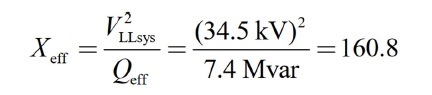
The effective impedance of the filter bank (Xeff) is calculated using the formula:
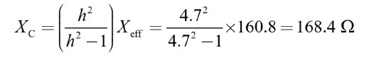
Once Xeff is known, the capacitive reactance at the fundamental frequency (Xc) is calculated using the formula:
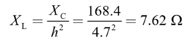
After obtaining the Xc value, the inductive reactance at the fundamental frequency (XL) can be calculated as follows:
Step 3: Optimize the Filter Configuration to Meet the Harmonic Guidelines
Once the capacitance and inductance values of the passive harmonic filter have been determined, the next step is to perform a harmonic analysis to evaluate whether the designed configuration is capable of reducing harmonic distortion according to applicable standards, such as those stipulated in IEEE Std 519 and IEEE Std 399 (Brown Book).
This analysis is typically performed using harmonic simulation software to model the filter’s response to various system conditions and actual harmonic spectra. The goal is to ensure that the harmonic voltages and currents in the system remain within standard tolerances.
During the evaluation process, the following points should be considered:
- If the harmonic distortion level still exceeds the threshold, then:
- The filter capacitance value can be increased to expand the filtering bandwidth
- The filter can be retuned to a more effective frequency
- Or more than one filter with different tuning frequencies may need to be added to cover the various dominant harmonic frequencies.
- If the performance is satisfactory, the design can proceed to the final component specification stage (capacitor, reactor, and resistor ratings).
Step 4: Determine the Filter Component Ratings
1) Harmonic Filter Capacitor
Determining the capacitor component rating in a passive harmonic filter begins by calculating the current at the filter’s fundamental frequency. For a wye (star) configuration, the calculation is as follows:
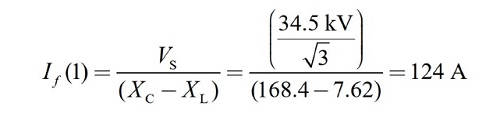
Where:
- VS is the system phase voltage (phase to neutral)
- XC is the capacitive reactance at the fundamental frequency
- XL is the inductive reactance at the fundamental frequency.
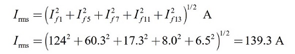
Next, the harmonic currents calculated are:
- 5th harmonic: 60.3 A
- 7th harmonic: 17.3 A
- 11th harmonic: 8.0 A
- 13th harmonic: 6.5 A
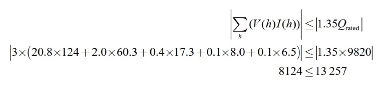
The total RMS current through the capacitor is calculated as:
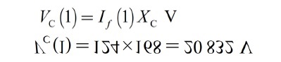
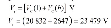
The fundamental voltage that appears on the capacitor is obtained from:
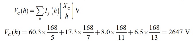
The harmonic voltage that appears on the capacitor due to the flow of harmonic current is obtained from:
So the total voltage that must be held by the capacitor is:
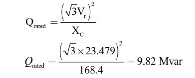
With the above voltage, the capacitor nameplate kVAR value can be calculated:
And the nominal current:
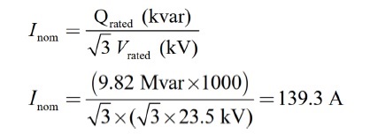
Where:
- Qrated is the 3-phase capacitor bank rating (MVAR)
- XC is the capacitive reactance of the capacitor bank, per phase (Ω).
This value closely matches the actual RMS current (139.3 A), indicating that this capacitor is safe to use according to IEEE Std 1036 (maximum 135% of nominal current).
Dielectric heating is evaluated using the following equation:
These results indicate that the capacitor design meets the dielectric heating limits with a safe margin.
2) Harmonic Filter Reactor
In this example, the filter reactor reactance has been previously calculated as 7.62 Ω (based on the 4.7th harmonic setting). Furthermore, the harmonic current generated by the load has also been obtained in the previous step. However, the system short-circuit current of 10 kA at the bus is not necessarily a direct reference for determining the harmonic reactor rating. Instead, the specific symmetrical short-circuit current value for the reactor is used, taking into account the combined impedance of the reactor and the system.
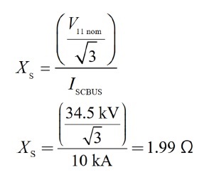
Once the source impedance is known, the value of the symmetric short-circuit current experienced by the filter reactor can be calculated using the following equation:
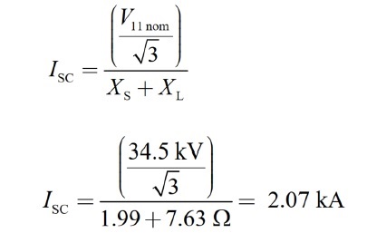
Therefore, the harmonic filter reactor must have a minimum short-circuit current rating of 2.07 kA under symmetrical conditions. This value is the minimum limit that must be achieved to ensure the reactor can withstand momentary disturbances without damage.
Additional Considerations:
- The duration of a fault will depend heavily on the characteristics of the protection system, such as the operating time of relays and circuit breakers.
- The asymmetrical short-circuit current rating can be determined, if necessary, using the system’s X/R ratio.
- In practice, the quality ratio (Q = X/R) of a harmonic filter reactor is typically designed above 50, although the exact value is not critical for most standard designs.
- To ensure design reliability, digital simulations can be performed to verify sensitivity to system parameter variations (see the simulation step in the previous step).
3) Circuit Breaker or Switch
It should be noted that the short-circuit current specifications for switching equipment differ from those for harmonic filter reactors.
In this example, the fault current on the bus is 10 kA, and this value is the primary reference for determining the short-circuit rating of the switching device (switch or breaker). Although capacitor switches are not designed to interrupt short-circuit currents (as circuit breakers are required to), they must still be able to withstand momentary fault currents, particularly during:
- Close-and-latch, which is when the switch is first activated and must close under conditions that may not be fully stable.
- Momentary current withstands, which is the ability to withstand the current momentarily before interruption (if necessary).
In addition, switch design must also consider the following worst-case scenarios:
- Maximum system voltage, including possible overvoltage due to switching or sudden load variations
- Capacitance tolerance, which can affect the inrush current value during capacitor switching
- Harmonic content, because high-frequency harmonic currents can amplify transient voltages during switching.
———————————————
Single-Tuned Filter Calculation Example
Using the same case study as the calculation example in IEEE Std. 1531-2020, the following are the Best Practice Steps in designing a single tuned passive filter:
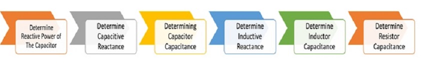
Step 1: Determine the Capacitor’s Reactive Power
The first step in designing a single-tuned harmonic filter is to determine the capacitive reactive power required to achieve the desired power factor. This requirement is calculated based on the change in system power factor before and after the harmonic filter is installed.
The effective reactive power of the harmonic filter (called Qeff) is generally calculated using the phase angle change approach due to the power factor change, with the following formula:
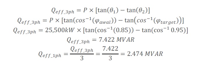
Notes:
- Qeff: Effective reactive power of the harmonic filter (VAR)
- P: System active power (W)
- φawal: Power factor before filter installation
- φtarget: Desired power factor
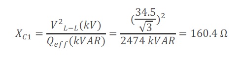
Step 2: Determine the Capacitive Reactance
When designing a single-tuned passive harmonic filter, the tuning frequency is generally adjusted to the dominant harmonic to be suppressed. The filter is typically tuned between 3% and 15% below the target harmonic frequency. This tuning is done to prevent parallel resonance with the system and to avoid excessive harmonic current absorption.
For example, in this case, the filter is designed to target the 11th harmonic. Therefore, the effective reactance of the capacitor can be calculated using the following equation:
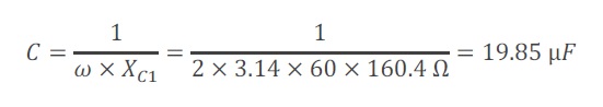
Step 3: Determine the Capacitance of the Capacitor
After obtaining the capacitive reactance value from the previous step, the next step in designing a single-tuned harmonic filter is to determine the capacitance (C) value of the capacitor bank to be used. This capacitance value is calculated based on the basic relationship between capacitive reactance and frequency, namely:
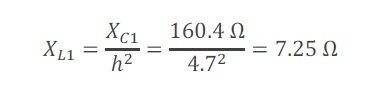
Step 4: Determine the Inductive Reactance
Once the capacitance is determined, the next step in designing a single-tuned filter is to determine the inductive reactance of the series reactor at the fundamental frequency. This value is crucial for forming a series resonance circuit with the capacitor, allowing the filter to optimally absorb harmonics of a specific order.
The inductive reactance calculation is performed using the formula:
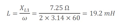
Step 5: Determine the Inductor’s Capacitance
Once the inductive reactance at the fundamental frequency is known, the next step is to calculate the inductance of the reactor used in the single-tuned filter circuit. This inductance value will determine the resonant frequency of the filter, so it must match the target harmonic order (in this example, the 11th harmonic, with a tuning of 10.8).
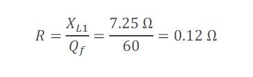
Step 6: Determine the Resistor’s Capacitance
Once the capacitor and inductor components have been determined, the next step in designing a single-tuned filter is determining the filter’s resistance (R) value.
By determining the quality factor (Qf), the equation for finding the resistance (R) value is as follows:
———————————————
References
- IEEE 3002.8-2018: Recommended Practice for Conducting Harmonic Studies and Analysis of Industrial and Commercial Power Systems
- IEEE 1531-2020: IEEE Guide for the Application and Specification of Harmonic Filters
- IEEE Std 519-2014: Recommended Practice and Requirements for Harmonic Control in Electric Power Systems
———————————————
 Contact Omazaki Engineering if you are looking for a designer or consultant for passive harmonic filter design or designing calculation services or passive harmonics filter design for electrical systems of industrial and commercial facilities in Indonesia and Southeast Asia.
———————————————